I have realised that the skill of engineering is almost entirely in managing trade offs, which I am still far from mastering. This is especially true in a synthesiser, musical instrument, or any project that combines creativity with a technical aspect as many conflicting aspects must be simultaneously juggled around: quality, cost, artistic style, size, weight, etc etc. Every solution has downsides, and more confusingly sometimes these downsides are secretly good. At the start of this project I was obsessed with keeping noise and distortion low in the circuit as this is what’s all over literature and is objectively the best practice. But actually, noise and distortion is to some extent the character of an electronic instrument and to eliminate it is to suck the soul out of the machine. It’s a rather annoying contradiction that after you design a theoretically perfect oscillator, you listen to it and it sounds dull and boring, but if you tweak some resistors and approach the rails of your op amp, or if you run things a little too hot into the vcas you start generating those lovely harmonics that’s associated with analogue synthesis.
Lines always have to be drawn though, and the hardest part is figuring out what actually does need to be electrically perfect; where to splash the cash on. For example it is probably audibly pleasing to have a certain amount of distortion in the output of an oscillator, but the control voltage and exponential convertor? That should be perfect for a usable musical instrument. Out of tune oscillators certainly have a place in art pop and ambient soundscapes but at a certain point, you’ll need an instrument that can hit a perfect 5th within a few cents and that circuitry certainly can’t have much noise or distortion. In my poly synth, the vast majority of the cost is directed towards the oscillator tuning: the monolithic transistors for the exponential convertor, the trimmer pots for tracking, and the extra circuitry for temperature compensation all add up quickly when you have 48 true analogue oscillators.
DACs
Another place in a poly synth that shouldn’t be overlooked in terms of quality is the digital to analogue conversion. A poly synth almost always has a form of microcontroller to distribute control voltages, generate envelopes and process MIDI information. There are a few ways to interface this into the analogue circuitry but all will have to involve some form of digital to analogue convertor (DAC) at some point.
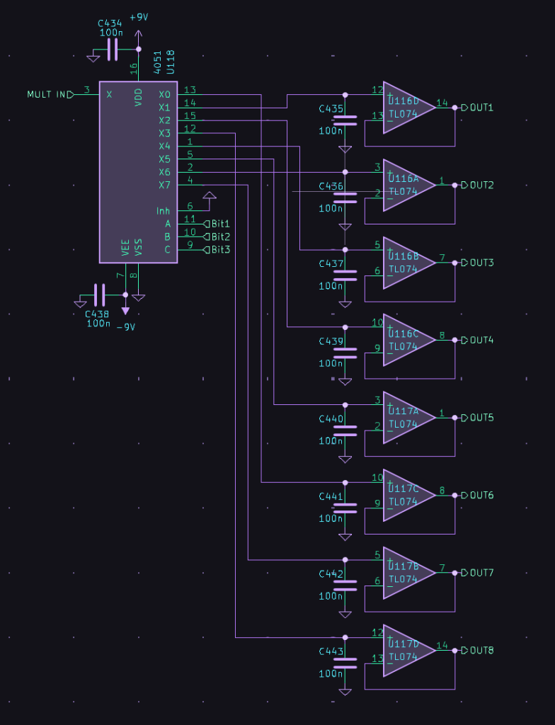
Historically DAC channels were expensive and so ye olde poly synths often had a single DAC channel with some clever sample and hold circuitry after. The DAC would output each control voltage for every parameter one after the other, settling in each CV for a set period (typically sub millisecond). This continuously varying signal would enter an array of demultiplexers which is an analogue switch with a single input and multiple outputs. Each output has a capacitor to ground and an op amp voltage follower subsequently. When a CV is momentarily outputted from the DAC as part of the continuous stream, the demux switches to the corresponding output, charging the capacitor to the DAC output voltage, effectively sampling that voltage. Once the DAC switches to the next CV, the demux switches with it, and the capacitor sees an open input of effectively infinite resistance. The input to the op amp is also high impedance, and as such the capacitor holds its voltage and the op amp mirrors this on its output, driving the analogue circuitry down the line with the sampled voltage.
Now in the real world of course, an op amp doesn’t have infinite input impedance and the capacitor also has a parasitic loss to ground. As such, the capacitor voltage slowly droops over time and so the voltage must be continuously updated by the DAC after it cycles through all the CVs. The exact timing of this cycle depends on many factors such as how long the DAC output takes to settle, how many CVs there are to update, how long the capacitor takes to charge, and how fast the capacitor droops but is usually on the order of several hundred to several thousand times per second. Better capacitors and op amps also offer less droop and faster acquisition times of the CV. The best op amps are CMOS input as these have higher input impedance than BJT variants, and the op amp should also have low noise and input offset. The best capacitors for sample and hold circuits should have low leakage (for low droop), and low dielectric absorption (for accuracy). You’ll often find quoted on the internet that the best capacitors have a polystyrene dielectric, but these are really expensive and big and not really made anymore. In practice, modern MLCC C0G capacitors perform well enough for this application and have adequate temperature characteristics. X7R caps can be used if you’re tight on budget, but for the sake of a few quid just get the best! Never use electrolytic for this application.
In the modern day, DAC channels are cheaper and you can find DAC chips with 8 or more channels for a relatively low cost. High end modern synths such as the Moog One use a dedicated DAC channel for every control voltage, but even with today’s low cost chips that can still add up if you’re not buying in bulk. The advantages, however, are threefold: that you don’t have to worry about timing the demux and DAC cycle, board space is reduced from not needing extra demux/opamp chips, and the output will be more accurate as there’s no opamp offset voltage.
For my synth, I opted for a meet in the middle approach (all about those tradeoffs!). My synth works around the rough eurorack standard (+/-12V rails, +/-5V CV) so I have an 8 channel DAC which natively outputs +/-5V signals so I don’t have to worry about scaling voltages. Each channel then go to 1:8 demux with a sample and hold circuit on the output of each. This allows for 64 parameters maximum which definitely covers the 48 or so my synth has. The opamps are all TL074s for their CMOS input, adequate specs and low low price. For the pitch CVs, I opted for an OPA4134 for its higher specs as those CVs are the most important. I only use 6 of the 8 channels of the DACs for sample and hold circuits, so I assigned the last two channels to the attack and release for the 3rd envelope generator I squeezed in at the end of the design process. You could argue that two of the pitch CVs should be on the direct output of the DACs if I have the option, but I thought I’d rather have 3 oscillators with the same CV signal chain. Theoretically if I’ve done my design right, it won’t be a problem anyway!
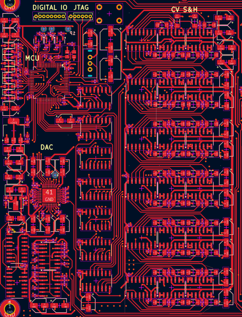
In this screenshot from the voice card PCB, you can see the DAC chip (middle left), the column of shift registers to the right to control the demux switching, and the sample and hold demux/opamps on the right with capacitors above/below. Not all traces are shown for demo purposes (on a 6 layer board it gets messy fast)
Bits and bollocks
There’s some debate over the amount of bits a DAC for CVs should have. Some people are caught up in the new sigma delta DACs that are apparently magically 24 or even 32 bits for very cheap but as Matthew from North Coast Synthesis explains in this article https://northcoastsynthesis.com/news/dacs-and-bit-count/, that’s kind of bollocks and doesn’t even matter. In reality, for CVs, 8-10 bits is enough for most parameters (attack, release, cutoff, etc), and 12 bits is enough for pitch. The DAC I chose (the LTC2686 for you nerds out there) is 16 bit and so is more than enough for any applications. If the output is +/-5V, and each volt represents an octave with my oscillators tuned to 1V/oct, then the resolution of a 16 bit DAC equates to around 0.18 cents of accuracy (65536 DAC for 10 volt range, 83.33mV per note = 546.13 DAC levels per note). Even with the opamp input offset, noise, and parasitics of the capacitor, I can safely say that the DAC won’t be the limiting factor in pitch precision compared to the temperature instability and tuning nightmares of the exponential convertor. But that’s for another day….

Leave a comment