Voice Card V2.2
Ups and downs over the past few months with regard to the synth. I’ve got a clearer picture about the overall architecture and added features, and made it more efficient generally. That being said, in the winter months it’s a struggle to keep focussed on the overall goal, especially with the relative failure of the recent voice card.
After receiving the card following nearly a month long wait in January I was eager to finally hear some audio from the full signal chain… alas it would not be so easy! I still have trouble soldering the DAC correctly with my rework station, those packages with tiny pins underneath are so hard to solder! I have half a mind to send the chips to JLCPCB and see if they can do it for me. I did eventually manage successful communication with the chip over SPI and the new oscillator design is running much cooler. The board also draws a lot less power after changing out select op amps for CMOS low power versions and refining pull-up resistors etc.
That’s kind of where the good news ends… about 10 minutes into coding the STM32 with the power on, the +9V rail collapsed which led a chip to short the -9V rail shortly after. There was a decent amount of smoke and most of the +/-9V chips were fried. I started removing chips to try and find what was causing the error as the regulators seemed not to be overheating so I figured it couldn’t be them. It seemed to be a random collection of chips which had all died so it was difficult to diagnose. My only tell was that the -9V rail has been consistently outputting -10.2V and no matter how I tend the feedback to the regulator the voltage doesn’t change, making me think there’s either a wiring issue shorting -9V to -12V or some other mistake on my part.
Voice Card V3.2
Whilst thinking over the issue I found a solution to all of my problems that made the board much cleaner in general. The reason I had been using the CD405x series of chips for my muxes was because I couldn’t find anything cheaper which could handle the voltages of the internal signal levels (+/-5V). The CD405x range can approach 18V across its rails hence the bipolar 9V rail solution. I always hated it – it felt janky and like bad engineering to me. Recently the price of the TMUX405x series seems to have dropped dramatically (or I didn’t notice how cheap they were before). For only a mild price increase they offer far superior specs including +/-12V rail support and 3V3 compatible logic (yay no more logic level translators!) but otherwise are a pin compatible replacement. I decided to go with that and with the DG442 to replace the CD4066. The DG442 is a bit more expensive but at this point I don’t mind a few extra pounds spent for something that doesn’t blow up, and that 9V rail has always been a problem. This now removes a bunch of chips and also frees up PCB space as I don’t need to route additional power rails everywhere – almost everything non-digital can come off the +/-12V power planes. The shift registers can also be updated to more modern 3V3 versions instead of the old ones which could support +/-9V for the CD405x but were slower and had higher quiescent current.
I feel much better about this now, there are far fewer things to go wrong. I also set about redesigning certain aspects on what is now V3.2 of the voice card. I AC coupled all audio VCAs which removed some trimmers, scaled back unnecessary power caps, and revised values so the BOM is shorter (the more variety of parts on a BOM, the more expensive the product as the assembly machine has to load more components). I removed the current source to the linearising diodes on most VCAs, resulting in the VCAs distorting quicker but in a nice, soft saturation way. I also added small series resistors to high speed data lines to reduce ringing so I could run at higher rates. I adjusted signal levels internally to make everything run hotter into the mixer and overdrive the filters slightly. Most modern synths implement a level of automatic compression here, and as more mixer sources are summed and levels turned up, the mixer adjusts its output volume to compensate slightly. Without this, the difference in level between a single sawtooth wave and all 4 oscillators, noise, ring mod, Wavefolder and EXT sources blasting at full whack (if you’d ever want such a thing) would be enormous and definitely clip the op amps down the chain. This is a feature to add later in software of course. I’ve also changed out some expensive precision multi-turn 3224W trimmers for the far more economical, one turn TC33X trimmers to reduce cost on less important things such as DC offsets of modulation.
Despite these changes, the most expensive part of the board – the trimmers – still remain at a staggering 68 pieces per voice card. This is mostly due to my design philosophy of rejecting digital modulation and over control. My modulation is fully discrete, as are all the parts on the voice card, and unfortunately this means trimmers are necessary to get the voices sounding similar. Almost all production modern synths by contrast are nearly trimmerless as they adjust digitally by varying the control voltage and watching the output waveform in real time. I suspect synths such as the Moog One do this to an insane level, as product design engineer at the time, Amos Gaynes, hinted to me. The oscillators on the One are capable of varying their shape from triangle to sawtooth, not by a simple mix knob, but by adjusting the ramp and fall time of the waveform independently from each other. Amos implied that this was achieved by constantly varying the control voltage many hundreds or thousands of times a second and watching the output waveform for any instability. Whilst quite the engineering marvel, it might as well be a digital oscillator with that level of overcontrol! I suspect the engineers pushed for a DCO to make that feature set work and some corporate up the chain told them to make it work as an analogue VCO for marketing reasons….
My synth still has an auto tune function to keep everything in tune by varying CV – it’s required at this scale or it would be a tuning mess. Mine, however, only calibrates on startup and when told to by the user via a conveniently placed button which takes around 2 seconds to complete. This could be changed so it overcontrols CV in real time, but I’m hoping the temperature compensation by implementing exponential convertors inspired by Ian Fritz’s “dial-a-tempco” will be sufficient to keep the oscillators in check most of the time. Recent tests have shown as little as 100ppm drift of the oscillators from 20-60 degrees C. The analogue sourced modulation also requires some trimmers, not only the trim for the discrete ADSR envelopes and LFOs, but also for the DC coupled VCAs that apply the modulation to the various destinations. It’s not much per block in the chain, but it all adds up for a voice card of this scale and results in this 68 trimmer mess. Unfortunately I can’t scale it back much more than I already have without going digital with the modulation (which would make the count of the trimmers drop to a neat 15 per voice card). I don’t mind doing a lot of calibration though. This obviously wouldn’t work in manufacturing on a large scale, but I’m only building one or two of these so I can afford some labour in calibration! I hope it’ll be worth it for the outcome.
After the significant overhaul to the PCB, there was a lot of unused space freed up from removing voltage regulators, logic level shifters and power traces. I decided to fill it with a few more features. Firstly, PW modulation. It’s one of those features I couldn’t really be bothered with before but I recognise is probably good to have on a flagship synth. It requires yet more routing of the analogue modulation sources, but there is now a knob to select modulation on OSCA and/or OSCB/C from LFO1, LFO2, EG1, or EG2. That should be plenty of options. Next I added a noise modulation source that can be mixed with LFO2 (fed from the audio noise source). This will add variation (subtle or not) to the destination similar to the Prophet 5’s LFO. The version I implemented also includes a basic VCF to the noise source so the rate of noise modulation can be controlled. I opted to called it “chaos mod” to differentiate between the audio noise. These features were easy wins, only requiring a small op amp/OTA to implement, or by using halves of dual op amps previously unused to realise.
It was also time to think about the wiring between the voice card and the motherboard. I previously had naively implemented an i2c line and told myself id think about it later. Now it is later and I’ve decided that the best solution is UART over RS485 which will provide rock solid differential performance and can go at the data speeds I want for extreme low latency. This required a change of the IO connector and addition of a transceiver to facilitate this. The digital IO is on a separate connector to the analogue to reduce crosstalk. There is also a sync pin for syncing oscillator phase and LFO2 retrigger across voice cards with super low latency.
I also have finalised the line code of data to be sent over UART from the motherboard to voice cards. Each packet consists of:
- 2 byte mask for voice card address: Each of the 16 bits represents a voice card. If 1, the voice card receives the parameter, if 0 it ignores it. This solution requires more bytes than a 4 bit address (0-15) but allows me to address multiple voice cards at the same time whilst retaining complete voice card independence.
- 1 byte parameter ID: 256 possible parameters/values. 0-99 is switches or on/off functions, 100-199 is knob parameters, 200-255 is special functions including note on/off, velocity, aftertouch, and LFO retriggers.
- 2 byte parameter data: 16 bit data value of parameter
- x bytes error correction and parity: still undecided how this will be handled. I may remove this in future or do a simple checksum that, if fails, result in the addressed voice cards ignore the packet.
This allows great flexibility with small packets. At the data rates I’m at this should be enough for perceptibly zero latency. The voice cards can technically talk back to the MCU when asked to. I think I’ll reserve this for after auto tune calibration (to confirm success/fail), but I may also allow a 2Hz query to each voice card where they respond with any errors/faults/temperatures. Each voice card now also has a small set of 8 dip switches to set the ID of the voice card over hardware as opposed to software. Obviously only 4 switches are required to set an ID between 0-15 but I’m sure the other 4 can be useful to trigger a calibration/testing state or other functions.
Future features
Whilst speaking to a friend about this, we came up with an idea that I’ve begun to put the hardware in to allow. The synth was always going to have a USB connection to PC which would allow debugging/console feedback from the master STM32. Now however, we are developing a bare bones VST plugin which will be able to control parameters and trigger notes/velocity. Think of it as a soft synth VST UI but controlling the hardware synth. This allows for easy DAW integration, MIDI to be sequenced in a piano roll, automation of parameters and other complex functions. We’ve decided to take it a step forward and also plan to integrate a small rpi server and an ADC on board the synth to allow internet connectivity. Then, when away from the physical synth, as long as it is powered and has an internet connection, you’ll be able to control it over the web with the same VST plugin and receive audio back. Current plans are to use a low latency OPUS codec to return audio, perhaps in mono, as a “draft” state which would allow low latency for protools projects and perhaps even playing pads with a keyboard over the internet. The VST would report the round trip delay and hopefully delay compensation in the DAW can account for this. Then, when happy with the settings, you can consolidate and the synth will transmit full fat stereo wav to the VST with a higher latency for rendering. This is obviously a gimmick but I think it’d be funny to have a wifi synth and it doesn’t seem immensely complicated at face value as the VST has to do very little in the way of audio processing. It will simply send sysex commands to the synth in the same packet type it’s expecting from the internal architecture, so the receiving chip on the synth can simply pass the messages along and the voice cards will respond accordingly. The Behringer DeepMind 12 springs to mind as a synth with similar functionality, I think there’s an iPad app to control parameters on it.
I’ve also added support for an in built ROMpler. This isn’t a core feature but a nice to have that I’ll add once the rest of the synth is working. It wouldn’t sample directly, but be loaded with sounds via an SD card with files prepped for it. I haven’t decided the format precisely but in preparation for it, there are 32 lines now running to the various voice cards from a new IO connector on the motherboard. This allows a stereo sampled sound possible per voice card from which would take the audio path of the EXT inputs if used. This means the mono summed sampler can pass through the filters on the voice card, or the stereo LR can pass directly to the VCA, or both if you fancy!
What now?
I’m aware this all sounds like feature creep, but this is only the implementation of connectors and traces to allow these features in the future. It would be mighty annoying to want to add these features later and have to order a new PCB. With that out the way I can focus on the voice cards once more. All these changes and revisions mean the current PCB layout have gotten very messy. I’m still thinking about how to approach this but I think it might be worth starting again with the PCB layout. Hopefully the voice card will end up a bit smaller and a bit more efficient. I’m hoping with the lack of voltage regulators and such power efficiency will also be improved. Current versions draw about 0.5A from each rail, but I’m hoping to get that down to 0.4A for a total of 12.8A drawn between both rails and 16 voice cards. Including the front panel and motherboard, I expect it’ll end up around 15-18A total draw, or 200W. That’s less than an amp from the wall at 230V! Obviously this redesign represents a massive amount of effort – I think it took me 2 ish months to complete the layout of V1.0 so I expect similar again. I’m happy to put in the effort though and triple check everything as it’s still north of £400 every time I order a prototype. This cost mostly represents the loading and assembling of parts and is a one time fee to load. Hence the cost if I were to do 16 boards, as opposed to 2 each time, only increases to £1600 for all 16 at a neat cost of £100 per voice card which I feel is reasonable.
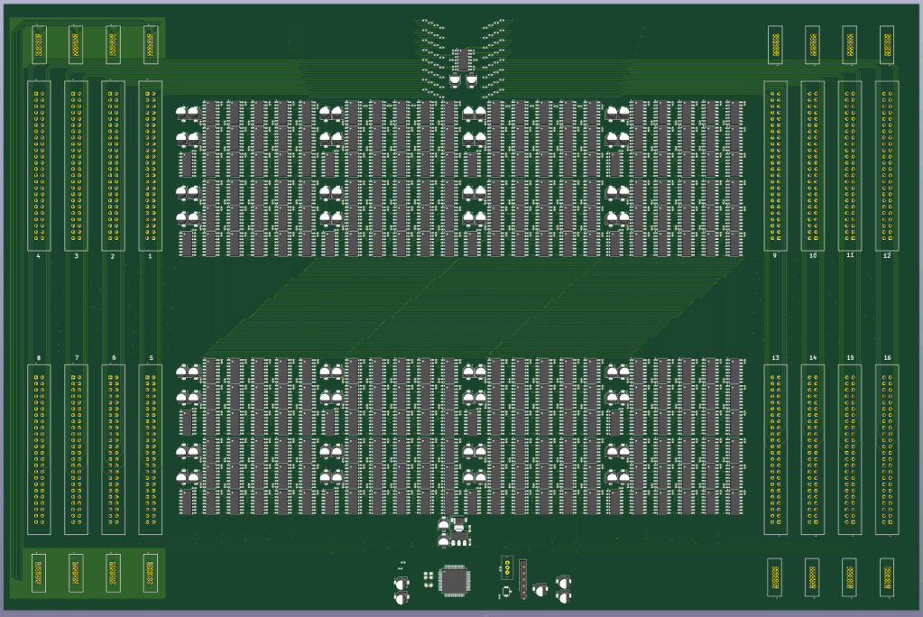
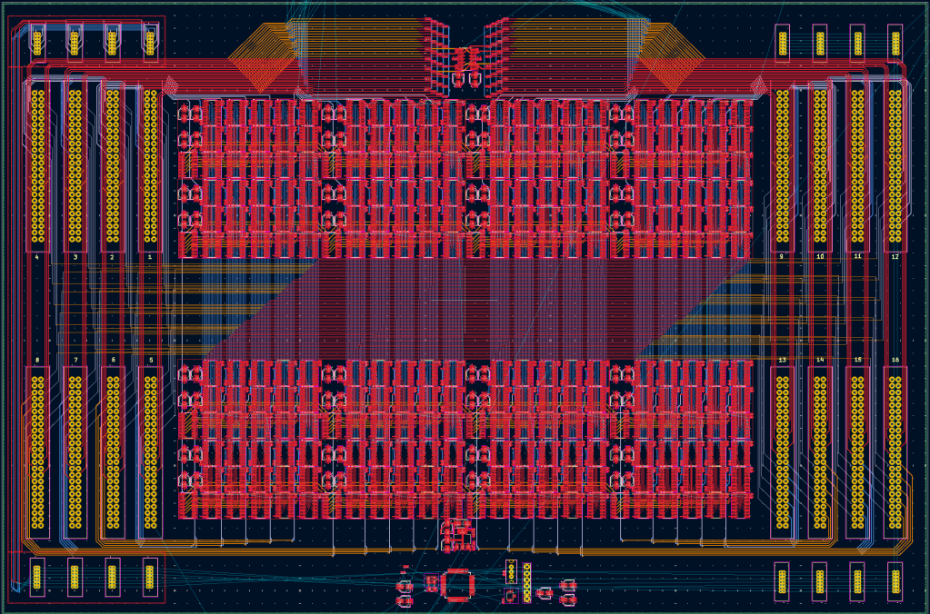
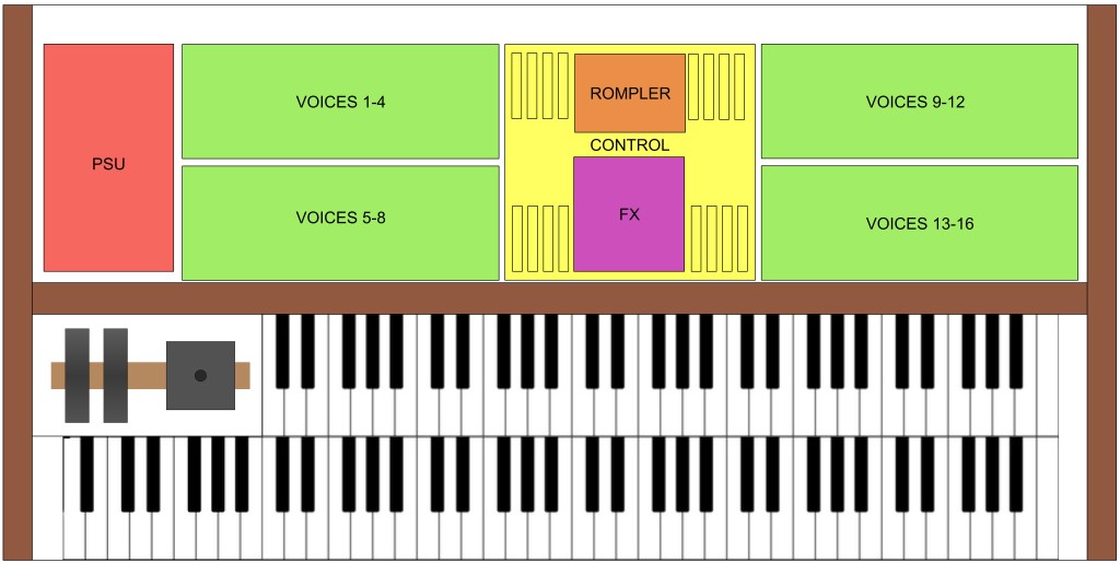
Finally, I’ve began work on the motherboard PCB that all the voice cards will connect to over DIN41612 connectors. There’s not a huge amount to say about it, it’s just a lots of traces and multiplexers. This is where the analogue routing of the modulation occurs and it requires a silly amount of multiplexers and shift registers to achieve this. The voice cards are stacked in 4 batches of 4 high to either side. This allows the PCB for the ROMpler, analogue FX, and rpi to be stacked on top of the multiplexers on the motherboard. There will also be connectors for the front panel PCB and the keyboard MIDI. That’s all then, until next time have some pretty pictures of the motherboard and layout to look at!